Timing a VW bus engine

This post is currently a draft
Quickstart
Pick the timing method you want to perform to see how it's done. Alternatively, read on for more information on timing a Type 4 engine.
| Timing procedure | Usage | Pros | Cons |
|---|---|---|---|
| Static | First motor start after a rebuild or distributor replacement. It's not yet possible to use one of the other two timing methods | Motor does not need to be started, easiest procedure of all | Not fully accurate. Timing needs to be double-checked and often readjusted using one of the other dynamic methods |
| Dynamic @ Idle | New motor, or if the distributor and motor have been well maintained or rebuilt | Accuracy, easy adjustment | Might not fully apply to old engines |
| Dynamic @ Full mech. advance | Recommended method for older engines or distributors and prolonged life | Accuracy, compensates timing for engine/distributor wear, adjustment made at a more demanding engine condition | Slightly more involved, as the throttle needs to be actuated during the reading |
On timing
Ignition timing of the engine, or simply timing in short, is the process of manually setting the point in time where the spark will occur to ignite the fuel/air mixture.
Rather than working with time units, the ignition point is measured as an angle relative to Top Dead Center for cylinder no. 1 at Compression time (TDC or TDCC). As such, the ignition is said to be:
- Advanced: when the spark occurs before TDC. The timing angle will be a positive value with a "BTDC" prefix. E.g. 7.5° BTDC
- Retarded: when the spark occurs after TDC. The timing angle will be a positive value with a "BTDC" prefix. E.g. 5° ATDC
[X] Advanced vs retarded timing
Timing is a maintenance procedure that needs to be performed whenever an engine is started for the first time (e.g. after a rebuild), or after adjusting the distributor point dwell.
It is important in the sense that the spark needs to occur at the right point in time to fully ignite the mixture and take advantage of the full energy of the combustion.
If your engine has not been adjusted as per the timing specs, here is what can happen:
- Ignition too advanced: spark occurs too early, generally before the piston has reached TDC and within the compression stroke. TODO: effects
- Ignition too retarded: spark occurs too late, generally after the piston has reached TDC and within the power stroke. TODO: effects
On timing methods
Static timing is the most basic of all. It is a rather crude but still valid means to either set the ignition timing to an adjustment good enough to start and run an engine satisfactorily for the first time, or to time an engine when a stroboscopic lamp is not available. It can also be used when installing a new distributor. Its strongest point lies in its simplicity. The weakest point is that it is simply an approximation of real world conditions: with the engine stopped, running conditions cannot be faithfully reproduced. Accuracy is also an issue, mainly due to the accummulated error of the mechanical plays involved and also due to the use of a test lamp as a measuring instrument. All that said, the result can be close enough to the timing achieved by other methods. Generally, it is done only once, and subsequent timing adjustments are of the dynamic kind.
Dynamic timing is the next step and the recommendation from VW and the ACVW community to do the adjustment under real world conditions. That is, with the engine running. There are two methods available which are essentially the same: they differ only in the point (i.e. engine condition) where the adjustment is being made. In both, we choose a characteristic condition as an anchor point to set the timing, and that point will be the baseline upon which the timing will be applied throughout the whole range. Generally, this anchor point will translate into a timing advance figure that will be added/substracted to a distributor's advance curve.
The actual measurement is performed with a stroboscopic lamp pointed to the crankcase scale, which is synchronized to lit at every spark plug #1 fire event. This ensures an accurate representation of the point in time when the spark is actually taking place (i.e. the firing point can actually be seen on the scale). The cyclic nature of the measurement also provides an intrinsic averaging of the readings.
- Dynamic timing at idle: if the chosen condition for the dynamic adjustment is at idle speed, we will be performing an idle timing adjustment as per factory recommendations. This is the best and easiest choice for an initial tuneup of a new engine, a low mileage one, or one that has been well maintained along with its distributor. This timing will be then carried out according to the distributor curve to the higher RPM ranges.
- Dynamic timing at full mechanical advance: given that new engine condition cannot be assumed for most buses on the road, and from empirical testing and accummulated experience, the ACVW community came up with a variation of the idle timing method that takes into account an aged engine/distributor and the most optimal setting for the life of a bus engine. The idea is to choose full throttle as the point of adjustment, which is where the engine will be doing most of its work. At full throttle (or as soon as ca. 3400 RPM are reached), the distributor's mechanical advance mechanism will be fully deployed. This gives the method its name: full mechanical advance, and it implies that the advance
Static timing
[[/vw-bus/timing/Distributor-wiring-3.jpg]]
What you will be doing:
- Setting the ignition point under static conditions with the engine stopped, as a means to be able to start the bus.
You will need:
- 10 mm wrench (to loosen/tighten distributor clamp nut)
- 22 mm wrench (to rotate the engine by hand)
- Test lamp or multimeter with continuity tester
Assumptions:
- Bus in neutral and e-brake set.
- The timing has either not been set before or cannot be guaranteed to be correct
- The TDC mark on the fan pulley has been found and optionally marked with some paint
- The distributor driveshaft has been installed and oriented to specs (12° from the case parting line)
- The crankcase is at TDC compression (TDCC) for cylinder #1 (distributor rotor pointing towards the engine compartment lid)
Steps:
- Look up and note down the idle timing advance for your engine. E.g. 7.5° BTDC
- Connect one end of the test lamp to one of the tabs of the coil's #1 terminal, also marked as "-".
- Connect the other end of the test lamp to a chassis ground point (e.g. the engine case). The test lamp has no polarity, so it does not matter which way round you connect it. The lamp will be lit only when the points are closed (i.e. during dwell), and it will be off when the points are open (i.e. during the spark event)
[./] Image shows test lamp connected
[ X] Image shows primary circuit - Remove the distributor cap, so that you can better watch the rotor.
- Also remove the main high tension cable in the middle of the cap and ground it while you are at it. More experienced folks will keep the distributor cap on, but we want to watch the rotor and the cam.
- Turn the ignition on, but do not start the engine. The lamp may or may not be lighting at this point, depending on the position of the points.
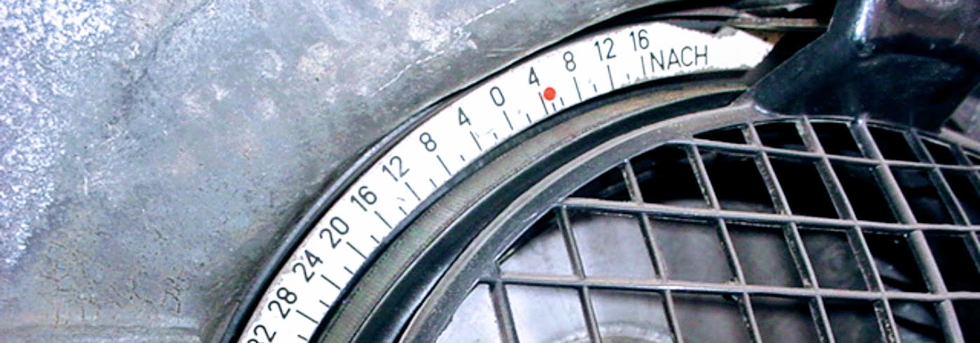
- Rotate the engine clockwise using the 22 mm wrench on the alternator pulley's nut, until the notch on the fan pulley aligns with the angle on the scale that you noted down on the previous step. If the crankcase is at TDCC (0° on the scale) and your idle timing advance spec is before TDCC, you will need nearly two clockwise revolutions of the crankcase to ensure you are at TDCC. You can optionally remove the cap of the alternator and watch where the rotor is. It will always be pointing towards the engine compartment lid at TDCC (TODO: single carb?). [X] Image shows scale at 7.5° (with an arrow) and alternator nut with wrench. A second arrow shows clockwise motion
Note: it's best to rotate the engine clockwise for two reasons: a) the engine actually turns clockwise. If you do the same manually, you don't have to account for the distributor gear play and your timing will be more accurate; b) you don't run the risk of loosening the alternator pulley nut while rotating it with the wrench. However, bearing all that in mind, you can actually turn the engine counterclockwise, simply be careful to not loose the alternator nut, and most importantly, when you do turn CCW, turn a bit more than you need (e.g. a quarter of a revolution) and then get to your intended position turning CW. This way you will have overcome the distributor play long before reaching the desired position, making your measurement accurate again. - Loosen up the distributor clamp nut using the 10 mm wrench. It should still be tight, but loose enough that you can rotate the distributor case by hand.
- Turn the distributor case in the direction that you need so that the notch on the case is aligned with the rotor pointer and the lamp lights up. That is roughly the point of maximum aperture of the points, which you can also see on the distributor cam. You are now in the ballpark, but we want to be more accurate.
- Turn the distributor case again, but this time CW until the test light goes off. We are now starting to do the fine adjustment.
- Turn the distributor case once more, this time CCW and aiming for the point where the light just barely goes on. If you've found it, move on to the next step. If not, iterate through this and the previous step until you hit the sweet spot moving the case CCW where the light is on, but just barely. We are aiming for the point where the points start opening and the spark is being fired. This is a simple process that appears long-winded when explained in words: you can watch this video on distributor case adjustment for static timing to easily grasp it visually. The video shows a Type 1 engine, but this part is exactly the same for a Type 4 engine.
- Tighten up the distributor clamp.
- Double-check the timing point with crankcase rotation: turn the crankcase 1/4 of a revolution CCW and then turn it CW until you reach the timing point in the scale.
- If the lamp is lit, you are all set. If not, repeat steps 6-11 until you achieve the finer setting.
- Replace the distributor cap and its connections.
- You should now be able to start your engine. Static timing is just an ancillary method to first start the engine. Do time it using one of the dynamic methods for a more accurate tuneup.
Dynamic timing at idle
What you will be doing:
- Setting the ignition point under dynamic conditions with the engine running at idle.
You will need:
- 10 mm wrench (to loosen/tighten distributor clamp nut)
- Stroboscopic lamp
Assumptions:
- Bus in neutral and e-brake set.
- Engine can be started.
- The TDC mark on the fan pulley has been found and optionally marked with some paint
- The distributor driveshaft has been installed and oriented to specs (12° from the case parting line)
Steps:
- Look up and note down the idle timing advance for your engine. E.g. 7.5° BTDC
- Connect the stroboscopic lamp as per its instructions. Generally the red wire is clipped to battery positive and the black wire to chassis ground. The third wire has a clamp where the bus' ignition wire for spark plug #1 goes through, in the direction of current marked on the clamp. Do check your lamp's instructions to be certain.
- Loosen up the distributor clamp nut using the 10 mm wrench. It should still be tight, but loose enough that you can rotate the distributor case by hand.
Dynamic timing at full mechanical advance
What you will be doing:
- Setting the ignition point under dynamic conditions with the engine running at full throttle.
You will need:
- A second person to either press the gas pedal or open the throttle
- 10 mm wrench (to loosen/tighten distributor clamp nut)
- Stroboscopic lamp
- Optionally a tach meter
Assumptions:
- Bus in neutral and e-brake set.
- Engine can be started.
- The TDC mark on the fan pulley has been found and optionally marked with some paint
- The distributor driveshaft has been installed and oriented to specs (12° from the case parting line)
Steps:
- Look up and note down the idle timing advance for your engine. E.g. 7.5° BTDC
- Connect the stroboscopic lamp as per its instructions. Generally the red wire is clipped to battery positive and the black wire to chassis ground. The third wire has a clamp where the bus' ignition wire for spark plug #1 goes through, in the direction of current marked on the clamp. Do check your lamp's instructions to be certain.
- Loosen up the distributor clamp nut using the 10 mm wrench. It should still be tight, but loose enough that you can rotate the distributor case by hand.
Appendix: finding TDC
With engine in the bus
[X] Image shows driveshaft 12°
[X] Image shows valve train status